Transitioning to 5-axis CNC machining unlocks extraordinary geometric freedom, yet it simultaneously introduces complex process troubleshooting challenges rarely encountered in 3-axis milling. Shop-floor engineers and CAM programmers frequently battle mysterious witness marks and dwell lines on 3D freeform surfaces, sudden uncommanded feedrate drops during simultaneous motion, parts that measure within 5 µm while clamped on the machine table only to warp by 50 µm the moment the vise is released, and actual cycle times that severely overshoot CAM software estimates.
Drawing directly from Chapters 7, 8, and 11 of Roland Zaugg's The Art & Science of 5-Axis Machining, systematic troubleshooting begins with a foundational engineering mindset: "Trust the Machine — Challenge Your Process First." Modern 5-axis machining centers are engineered and certified under rigorous ISO quality standards; in the vast majority of cases, dimensional non-conformance and surface defects stem not from machine tool failure, but from a disconnect between CAM programming assumptions and physical machining reality.
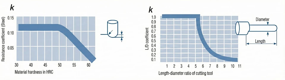
This comprehensive guide provides actionable engineering solutions to the four most critical challenges in 5-axis manufacturing—bridging the gap between digital CAM simulation and the physical laws of cutting mechanics, multi-axis servo dynamics, and structural workholding.
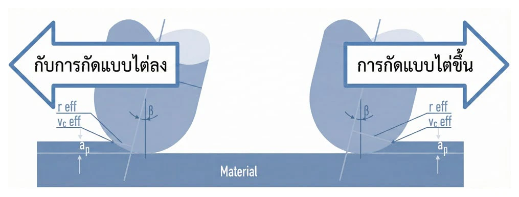
One of the most frequent surface finish defects in 3D contour milling—characterized by cloudy witness bands, micro-tearing, and premature tool tip breakdown—stems from "The Zero-Cutting-Speed Problem (Vc = 0)" (pp. 96–97). When a ball-nose end mill is oriented normal (0° tilt) to a flat or gently contoured surface, the exact apex (center tip) of the cutter has an effective rotational radius of zero (reff = 0 mm). Consequently, the cutting velocity at the tool center drops to Vc = 0 m/min.
Within this central "dead spot," the cutting edges cannot shear metal cleanly. Instead, the tool tip crushes, smears, and micro-burnishes the workpiece material, generating extreme localized friction heat, work-hardening the surface layer, and rapidly fracturing the carbide substrate at the chisel center.
The 5-Axis Engineering Solution: By leveraging simultaneous or indexed 5-axis kinematics to maintain a continuous 10°–15° (up to 20°) lead and/or tilt angle (β) relative to the surface normal, the contact zone is shifted away from the dead-center apex onto the peripheral radius of the ball nose. When combined with Climb Milling (Down-Milling) and an Isotropic Surface Strategy—where feed per tooth is matched to the radial stepover (fz ≈ ae, governing theoretical roughness height via Rth ≈ ae2 / (8r))—the cutting physics transform dramatically (p. 97):
| Finishing Parameter | 0° Normal Orientation / Conventional Milling | 10°–15° 5-Axis Lead/Tilt + Climb Milling | Engineering & Shop-Floor Impact |
|---|---|---|---|
| Cutting Velocity at Tool Tip | Vc = 0 m/min (Central Dead Spot) | Zero-speed apex completely lifted off surface | Replaces material crushing/smearing with clean shear action |
| Effective Cutter Radius (reff) | 0.94 mm (Book benchmark, p. 97) | 3.27 mm (+248% Effective Radius) | Engages stronger flute section with larger chip chambers |
| Effective Cutting Speed (Veff) | 30 m/min | 103 m/min (+243% Effective Velocity) | Triples tool life without increasing spindle bearing RPM |
| 3D Surface Homogeneity | Anisotropic bands, micro-burnishing marks | Uniform isotropic scallop structure (fz ≈ ae) | Eliminates manual bench polishing on complex molds & dies |
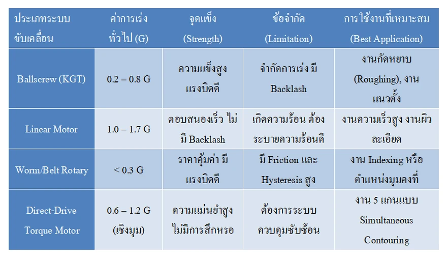
A pervasive frustration in simultaneous 5-axis machining occurs when a program commanded at a constant surface feedrate (e.g., vf = 4,000 mm/min) unexpectedly stutters, decelerates in mid-cut, and leaves visible dwell marks or surface gouges on the part. As explained in Chapter 8 (pp. 99–102), this phenomenon is governed by "The Limiting Axis Rule" and the non-uniform dynamic architecture of 5-axis machine tools.
Unlike standard 3-axis machines, a single 5-axis machining center integrates vastly different drive technologies within the same kinematic chain: linear X/Y/Z axes may utilize ballscrews (0.2–0.5 G) or frictionless linear motors (0.8–1.5 G), while rotary/swivel A/B/C axes rely on worm gears, belt transmissions, or direct-drive torque motors (0.3–1.2 G) carrying heavy table and fixture inertia. During simultaneous 5-axis interpolation, all axes must arrive at each programmed NC block synchronously. Consequently, the slowest axis in any given motion segment becomes the leading (limiting) axis that dictates the actual interpolated feedrate of the entire machine.
Whenever a CAM toolpath commands rapid rotary angular reversals over short linear chord segments (such as near a kinematic pole/singularity or across tight radii), the rotary axis hits its physical acceleration ceiling. The CNC controller automatically de-rates the overall vector feedrate to prevent following error. As actual table feed plummets while spindle RPM remains constant, the true feed per tooth (fz) collapses—causing the cutter to rub, thermally glaze the surface, and leave a dwell witness mark. Motion smoothness is further governed by Jerk (j = da/dt, in m/s³), the rate of change of acceleration (p. 99):
Actionable Shop-Floor & CAM Solutions:
| Axis Drive Architecture | Typical Max Acceleration | Typical Jerk Range (j = da/dt) | Dynamic Behavior & 5-Axis Machining Impact |
|---|---|---|---|
| Ballscrew Drive (BS) | 0.2 – 0.5 G (≈ 2 – 5 m/s²) | 80 – 250 m/s³ | High static stiffness and positioning accuracy, but limited acceleration due to mechanical inertia |
| Belt Drive (BD) | 0.4 – 0.8 G (≈ 4 – 8 m/s²) | 150 – 400 m/s³ | Cost-effective for medium speeds; elastic compliance limits ultra-high dynamic reversals |
| Linear Motor (LMD) | 0.8 – 1.5+ G (≈ 8 – 15 m/s²) | 300 – 800 m/s³ | Frictionless, ultra-fast response; requires active thermal cooling and high-damping machine beds |
| Torque Motor (DD Rotary) | 0.3 – 1.2 G (≈ 3 – 12 m/s²) | 150 – 600 m/s³ | Backlash-free angular precision; effective acceleration drops if heavy fixtures sit far from CoR |
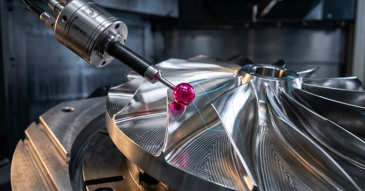
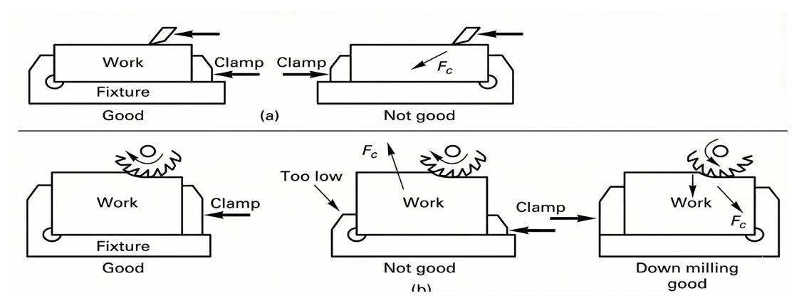
One of the most costly troubleshooting scenarios in precision 5-axis manufacturing occurs when a part inspected on-machine with a 3D touch probe measures well within ±5 µm of nominal tolerance—yet springs out of tolerance by 50 µm the instant the vise jaws are released! Drawing from Chapter 7 (pp. 90–91) and Chapter 11 (pp. 144–149), this failure is driven by two compounding physical mechanisms: elastic clamping distortion from excessive vise pressure and internal residual stress release during bulk material removal.
When an operator over-torques a mechanical vise to secure a raw billet against heavy roughing forces, the workpiece elastically bows or compresses. As the end mill machines precise flat or contoured datums onto this elastically deformed state, the geometry is only true while under compression. Once unclamped, the part elastically rebounds (springs back), warping the finished surfaces. Furthermore, mounting heavy workpieces or fixtures off-center on the machine table—far from the Rotary Center of Rotation (CoR)—induces non-linear structural bed deflection and magnifies rotary positioning errors (arc-seconds of angular deviation multiplied by radial distance).
Systematic Engineering Solutions for Distortion-Free 5-Axis Workholding (pp. 144–149):
| Shop-Floor Symptom | Metrology Matrix Classification | Engineering Root Cause | Systematic Corrective Action |
|---|---|---|---|
| Measures ±5 µm clamped, warps 50 µm unclamped | In-process elastic distortion & stress release | Excessive clamping force + asymmetric release of internal billet stresses | Use 3-point kinematic support; unclamp/relax after roughing, re-clamp at low force, and re-probe before finishing |
| Consistent dimensional offset across all parts | Low Accuracy, High Precision (Systematic Shift) |
Zero-point chuck offset or rotary pivot kinematic model shift | Run automated kinematic calibration (e.g., KinematicsOpt) and update work offset before finishing |
| Random part-to-part dimensional scatter | Low Accuracy, Low Precision (Process Instability) |
Chips trapped on clamping locating surfaces, thermal drift, or dirty probe measurement | Ensure generous fixture chip clearance, run machine warm-up, stabilize coolant temperature, and clean before probing |
To illustrate how deeply programmer strategy dictates 5-axis manufacturing success, Roland Zaugg presents a landmark shop-floor benchmark in Chapter 8 titled "2 Programmers, 2 Results" (pp. 103–106). Two experienced CAM programmers were given the exact same "Hard Facts": the same simultaneous 5-axis machining center (GFMS HEM 700U), the same aluminum alloy stock, and the exact same Ø 8 mm solid carbide ball-nose end mill to machine a hemispherical half-shell cavity (Ø 80 mm diameter × 40 mm deep—scaling from a 9 min vs. 5 min single-cavity test to a 78 min vs. 43 min full multi-cavity production cycle).
Programmer #1 (Conventional 3-Axis Mindset — 78 Min Full Cycle / 9 Min Single Cavity):
Programmer #2 (Holistic 5-Axis Optimization — 43 Min Full Cycle / 5 Min Single Cavity, -45% Cycle Time!):
| Benchmark Criterion | Programmer #1 (3-Axis Thinking + 90° Normal) | Programmer #2 (5-Axis Inclination 25° Tilt / 15° Lead) | Engineering Performance Gain |
|---|---|---|---|
| Roughing Strategy & Parameters | 3-Axis Cavity Milling (ae = 2.5 mm, ap = 2.5 mm) |
4/5-Axis Full-Flute Projection (ae = 0.5 mm, ap = 16 mm × 2 steps) |
-60% Roughing Time (5 min → 2 min per cavity); full flute utilization |
| Finishing Strategy & Contact Zone | 4-Axis Spiral at 90° to surface (Contact sweeps across entire ball arc) |
5-Axis Simultaneous at 25° + 15° (Fixed contact point on cutter radius) |
100% constant Veff; eliminates ball-nose radius segmenting errors |
| Total Machining Cycle Time | Single Test Cavity: 9 minutes Full Production Part: 78 minutes |
Single Test Cavity: 5 minutes Full Production Part: 43 minutes |
-45% Total Cycle Time Reduction using the exact same machine and tool |
| Resulting Surface Quality | Floor vibration chatter marks and visible contour segmentation rings | Flawless, mirror-homogeneous surface finish free of witness lines | Proves Zaugg's maxim: "People and process understanding make the difference" |
© 2022 Machine Tech Co., Ltd. All Rights Reserved. Web design by 1001click.