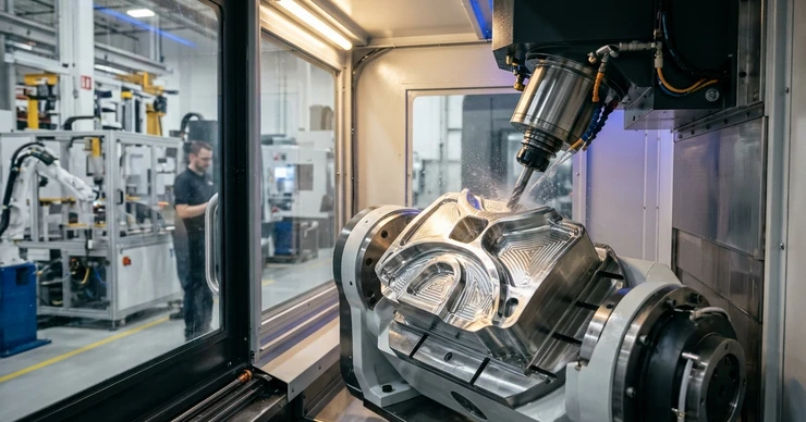
In modern 5-axis CNC machining—characterized by extended tool overhangs (stick-out) required to clear deep cavity walls at compound tilt angles and high spindle speeds ranging from 12,000 to over 30,000–40,000 RPM—the tool holder is never a passive mechanical adapter. As established in Chapter 10 of Roland Zaugg's The Art & Science of 5-Axis Machining, the tool holder system is a precision dynamic transmission element that directly dictates dimensional accuracy, 3D surface finish homogeneity, cutting tool longevity, and spindle bearing survival.
Unlike conventional 3-axis milling where cutting force vectors remain relatively predictable, simultaneous 5-axis machining subjects the tool assembly to continuously shifting tool vectors, variable bending moments, and tight geometric clearances. Any radial compliance, micro-runout, or rotational imbalance at the spindle nose is amplified by the tool's gauge length, triggering regenerative chatter, uneven flute wear, and catastrophic spindle bearing fatigue.
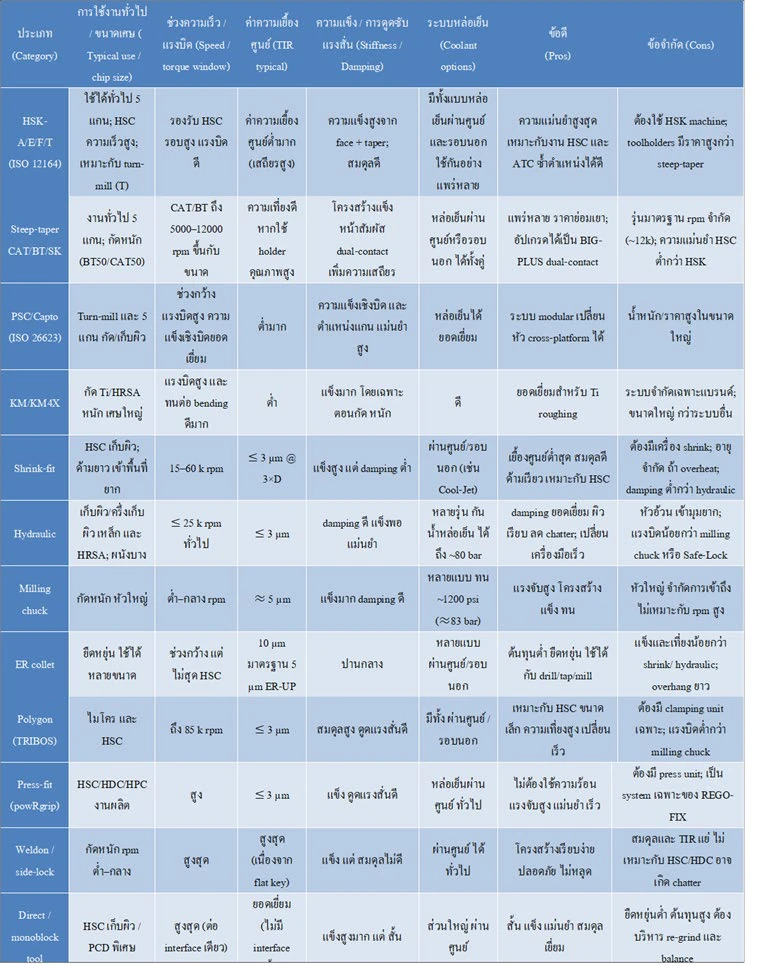
Achieving micron-level process stability requires treating the tooling assembly as an integrated dynamic system governed by two equally critical interfaces: the First Interface (Spindle-to-Holder Interface), which governs macro-stiffness, axial Z-positioning stability under centrifugal force, and automatic tool changer (ATC) repeatability; and the Second Interface (Holder-to-Tool Clamping Technology), which controls micro-runout (TIR), structural vibration damping, slim-profile accessibility, and axial pull-out security.
In high-precision 5-axis machining, the spindle-to-holder interface represents "The First Interface"—the foundational mechanical junction responsible for transmitting spindle torque, rotational symmetry, and geometric alignment to the cutting edge. Both the spindle taper bore and the tool holder shank are precision-ground to sub-micron tolerances because even a minuscule angular tilt at the gauge line is magnified proportionally over long tool overhangs into severe radial runout and Tool Center Point (TCP) deviation.
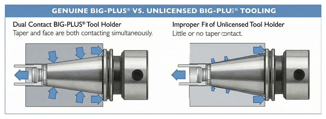
The fundamental physical limitation of conventional 7:24 steep-taper interfaces (standard SK, BT, and CAT)—which rely exclusively on taper contact while leaving an intentional axial gap between the flange face and the spindle nose—becomes acute at spindle speeds exceeding 12,000 RPM. Because centrifugal force increases with the square of rotational velocity (Fc ∝ ω2), the thinner outer wall of the rotating spindle nose expands radially outward significantly faster than the solid steel taper of the tool holder.
As the spindle bore bells outward under high-RPM centrifugal loads, the constant axial tension of the drawbar pulls the steep-taper holder deeper into the spindle cavity. This phenomenon, known as "Z-axis drawbar pullback," triggers three critical failures in 5-axis operations:
Real-World Shop-Floor Case Study: Roland Zaugg documents an aerospace facility operating a BT50 spindle where minor chip contamination and fretting corrosion on the interface induced a persistent 0.02 mm (20 µm) runout across all holders—resulting in total spindle bearing failure after just 2,000 operating hours. Eliminating these failure modes requires simultaneous taper-and-face contact interfaces and strict daily taper cleaning protocols using lint-free wipes and alcohol.
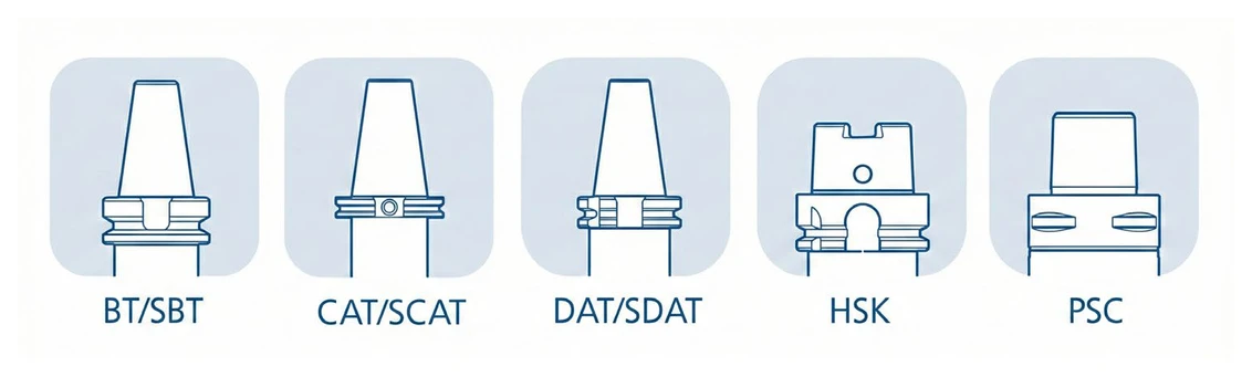
To overcome the centrifugal expansion and radial compliance limitations of conventional tapers, modern 5-axis machine tools utilize spindle interfaces engineered for simultaneous taper and flange face contact. Selecting the optimal spindle interface requires matching mechanical stiffness, rotational speed capability, and torque transmission to the target application:
| Technical Criterion | Standard Steep Taper (SK / BT / CAT) | BIG-PLUS Dual-Contact (BBT / BCV) | HSK-A / HSK-E (ISO 12164) | PSC "Capto" (ISO 26623) / KM4X |
|---|---|---|---|---|
| Contact Mechanism | 7:24 Taper-Only Contact | Simultaneous 7:24 Taper + Flange Face | 1:10 Hollow Taper + Flange Face | Polygonal Taper + Flange Face |
| Practical RPM Ceiling | ≤ 12,000 RPM (Z-pullback onset) | 15,000 – 20,000+ RPM | HSK-A: ~25,000–30,000 RPM HSK-E: 40,000–60,000+ RPM |
12,000 – 25,000 RPM (size C4–C10 dependent) |
| High-RPM Z-Axis Stability | Poor (axial drawbar pullback) | High (flange face blocks axial pull-in) | Excellent (hollow wall expands with spindle) | Excellent (positive axial face location) |
| Torque & Bending Rigidity | Moderate (high only in low-RPM #50 taper) | Very High (flange support resists bending) | High (lightweight, fast ATC response) | Maximum (keyless polygon torque transmission) |
| Primary 5-Axis Applications | General job-shop milling at moderate speeds | Heavy mold & die, retrofit BT/CAT upgrades | High-speed 5-axis finishing, die/mold, aero, medical | Mill-Turn centers, heavy aerospace Ti/HRSA structural roughing |
While the spindle interface dictates macro-stiffness, "The Second Interface" (Holder-to-Tool Clamping Mechanism) directly governs cutting tool concentricity (micro-runout), harmonic vibration damping, nose clearance contour in deep 5-axis cavities, and axial pull-out security. Chapter 10 of Roland Zaugg's work evaluates the five primary clamping technologies used in modern 5-axis production:
h6-tolerance carbide shank, shrink-fit holders create a 360° interference friction fit upon cooling that behaves like a solid monoblock. They deliver TIR ≤ 3 µm at 3×D, predictable G2.5 balance up to 60,000 RPM, and the slimmest possible nose contour for reaching deep 5-axis undercuts and steep cavity walls. When combined with positive axial form-locking grooves (such as HAIMER Safe-Lock), shrink-fit chucks achieve 100% pull-out security for heavy titanium roughing. Their primary trade-off is lower intrinsic vibration damping compared to hydraulic chucks and gradual material fatigue after repeated thermal cycles.| Clamping Technology | Runout (TIR @ 3×D) | Clamping Torque & Rigidity | Vibration Damping | 5-Axis Nose Clearance | Optimal 5-Axis Application |
|---|---|---|---|---|---|
| Thermal Shrink-Fit (+ Safe-Lock) |
≤ 3 µm | Very High (Maximum with Safe-Lock) | Low–Moderate (Monolithic feel) | Best-in-Class (Ultra-slim contour) | Deep 5-axis cavity access, HSC/HDC, heavy HPC roughing (with Safe-Lock) |
| Hydraulic Expansion (e.g., SCHUNK TENDO) |
≤ 3 µm | Moderate–High | Outstanding (Oil chamber damping) | Moderate–Good (Slim variants available) | Thin-wall finishing, HRSA/Titanium semi-finish & finish, precision drilling |
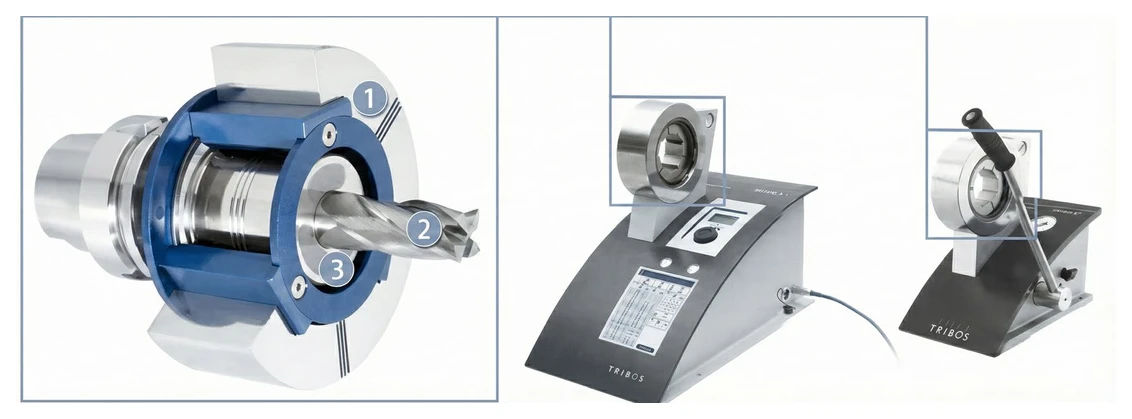
| Polygonal Elastic (SCHUNK TRIBOS) |
≤ 3 µm | Moderate (Small shank focus) | Very Good (Seamless body) | Excellent (Ultra-slim micro profiles) | Micro-machining (< 6 mm), ultra-high RPM HSC up to 85,000 RPM |
| Mechanical Press-Fit (REGO-FIX powRgrip) |
≤ 3 µm | Highest (Up to 5x torque, cold press) | Excellent (Dual-interface damping) | Very Good | Universal high-end 5-axis roughing (HPC/HDC) and mirror finishing |
| Precision Collets (ER-UP / micRun) |
≤ 3–5 µm (Std ER ≤ 10 µm) |
Moderate | Moderate | Moderate (Limited by clamping nut) | Drilling, tapping, and flexible semi-finishing operations |
Even the most sophisticated 5-axis CAM toolpath and premium PVD-coated solid carbide end mill cannot compensate for poor tool holding dynamics. In Chapter 10 (pp. 131–134), Roland Zaugg highlights the two invisible parameters that separate world-class 5-axis machining from chronic process failure: Total Indicated Runout (TIR) and Dynamic Balancing.
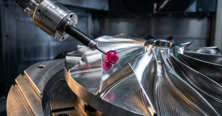
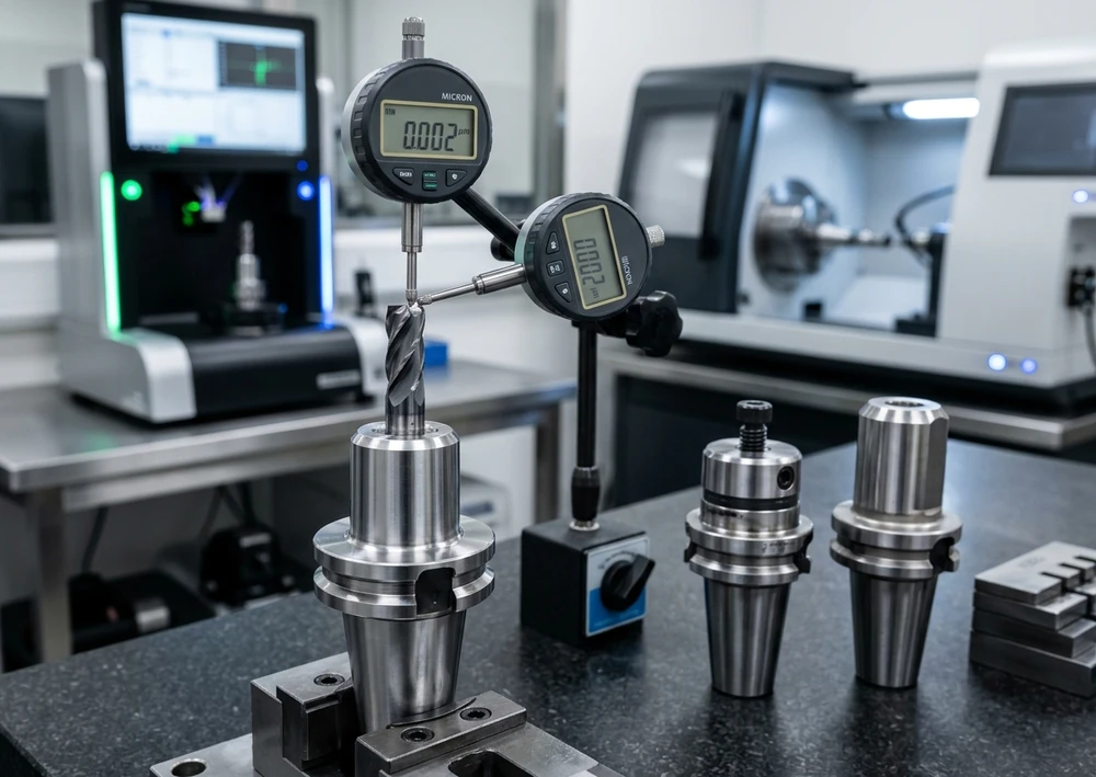
1. The Golden Rule of Total Indicated Runout (TIR ≤ 3 µm): TIR measures the total radial deviation of the cutting edges from the true axis of rotation, evaluated at a standard overhang of 3×D from the holder nose. As a fundamental rule, maximum runout must never exceed 1% of the cutting tool diameter (e.g., a Ø 0.5 mm micro-end mill requires TIR ≤ 5 µm, while high-performance 5-axis finishing demands TIR ≤ 3 µm). Quantitative shop-floor data reveals a stark reality:
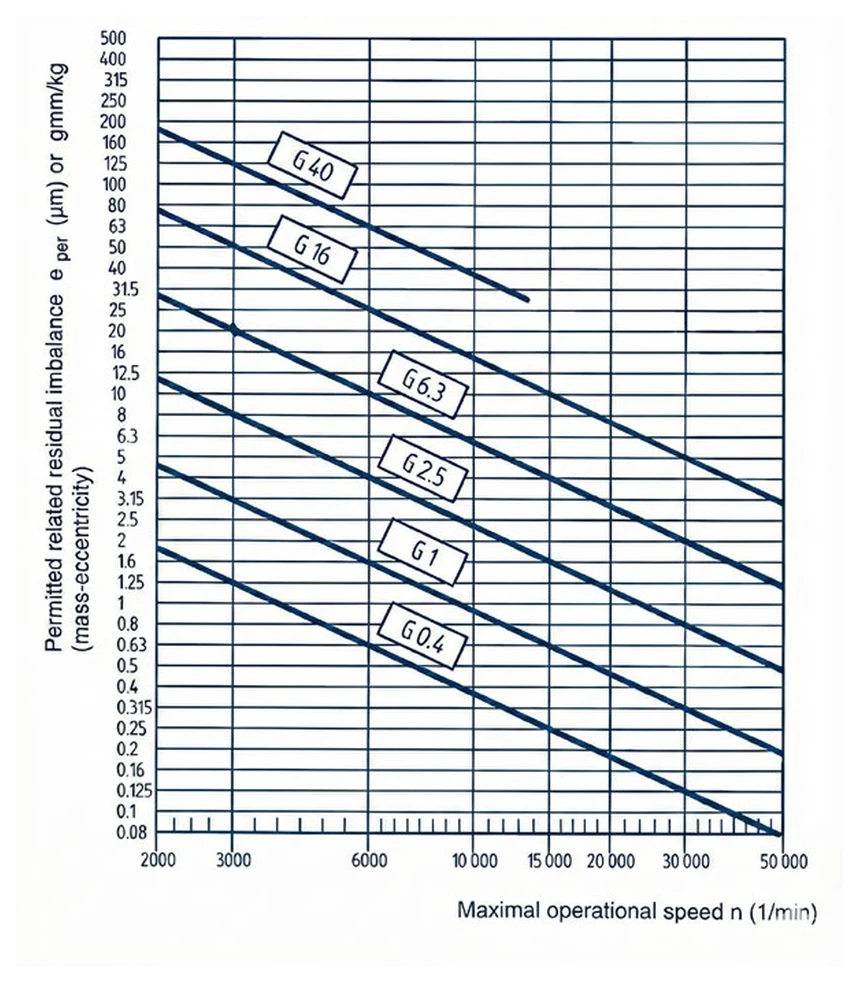
2. Dynamic Balancing to ISO 1940-1 (G2.5 at 20,000–25,000 RPM): Rotational unbalance (U, measured in g·mm) arises from asymmetrical mass distribution in drive keys, clamping nuts, set screws, or cutter flute geometry. Because centrifugal force scales with the square of rotational speed (F = U · ω2), at 20,000 RPM, a tiny unbalance of just 1 g·mm generates over 40 N of centrifugal force—equivalent to a 4 kg hammer continuously pounding the spindle bearings at 333 Hz! ISO 1940-1 defines the mandatory balance quality grades:
| Control Parameter | 5-Axis Target Specification | Quantitative Impact of Neglect | Mandatory Shop-Floor Protocol |
|---|---|---|---|
| Total Indicated Runout (TIR @ 3×D) | ≤ 3 µm for HSC/HDC finishing (and strictly ≤ 1% of tool Ø) |
10 µm TIR cuts tool life by > 50%; uneven chip load causes witness marks & chatter | Verify TIR at 3×D on the presetting station before every run and immediately after any overload/crash |
| Dynamic Balance Grade (ISO 1940-1) | G2.5 at 20,000–25,000 RPM (G1.0 for Aero/Medical) |
1 g·mm at 20,000 RPM exerts > 40 N radial load on spindle bearings, inducing harmonic chatter | Perform 2-plane dynamic balancing on the complete assembly (holder + tool + pull stud) above 12,000 RPM |
| Interface & Drawbar Integrity | Zero fretting corrosion; OEM drawbar retention force | Fretting causes 0.02 mm tilt error and catastrophic spindle failure within 2,000 hours | Clean taper & flange surfaces with lint-free wipes + alcohol at every change; log drawbar force quarterly |
© 2022 Machine Tech Co., Ltd. All Rights Reserved. Web design by 1001click.