In an era where high-precision manufacturing faces intense cost pressures, compressed delivery schedules, and increasingly complex part geometries, relying solely on traditional 3-Axis CNC Machining quickly becomes a major shop-floor bottleneck. Transitioning to 5-Axis Machining—encompassing both tilted working plane positioning (3+2 Indexed Machining) and full 5-Axis Simultaneous Machining—is no longer reserved purely for exotic turbine blades. Today, it is the primary strategic lever for maximizing spindle productivity and achieving rapid, measurable Return on Investment (ROI).
Grounded in the engineering principles of Roland Zaugg’s The Art & Science of 5-Axis Machining, the decisive advantage of 5-axis technology lies in the “Done-in-One” philosophy: completing five sides of a prismatic or freeform workpiece in a single clamping operation. This eliminates redundant setups, eradicates datum-transfer tolerance stack-up, and allows programmers to deploy shorter, vastly more rigid cutting tools.
To unlock the full potential of 5-axis machining, manufacturing engineers must first understand the kinematic leap from 3-axis to 5-axis coordinate systems. On a conventional 3-axis Vertical Machining Center (VMC), motion is restricted to three orthogonal linear axes: X (left-right), Y (front-back), and Z (up-down along the spindle axis). Because the tool vector remains permanently fixed parallel to the Z-axis, any undercut or side feature requires stopping the spindle and manually flipping the part.
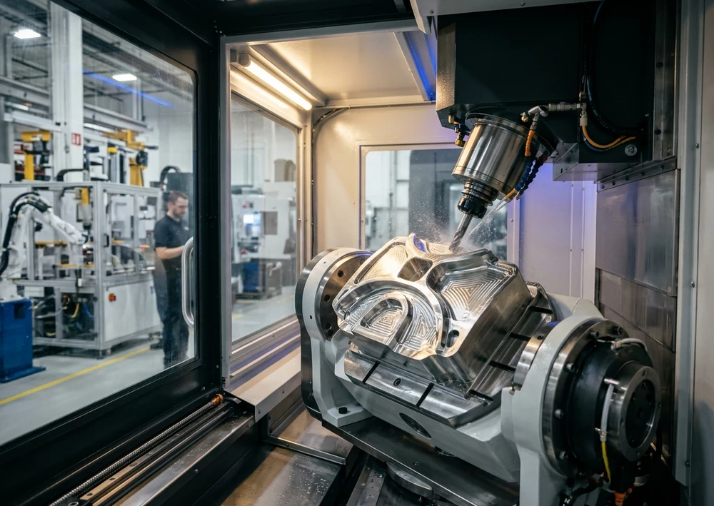
A 5-Axis CNC Machining Center introduces two rotary axes selected from Axis A (rotation around X), Axis B (rotation around Y), and Axis C (rotation around Z). Combining three linear axes with two rotary axes grants full spatial orientation of both the workpiece and the cutting tool across five faces in one clamping.
G54–G59) that links the CAD/CAM origin to the physical stock on the rotary table.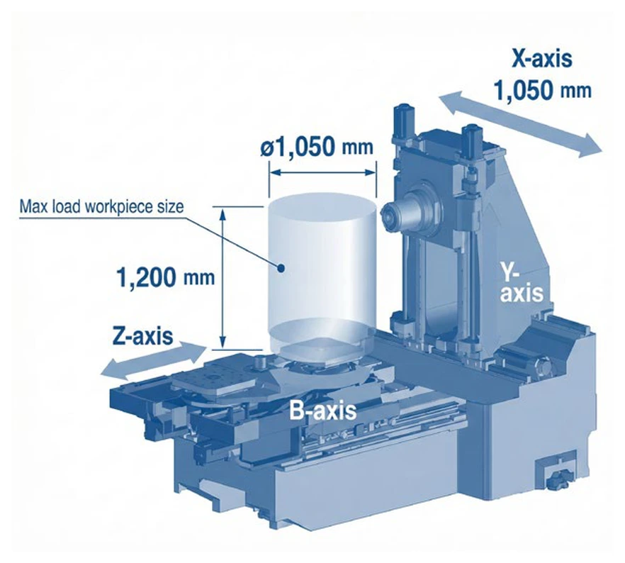
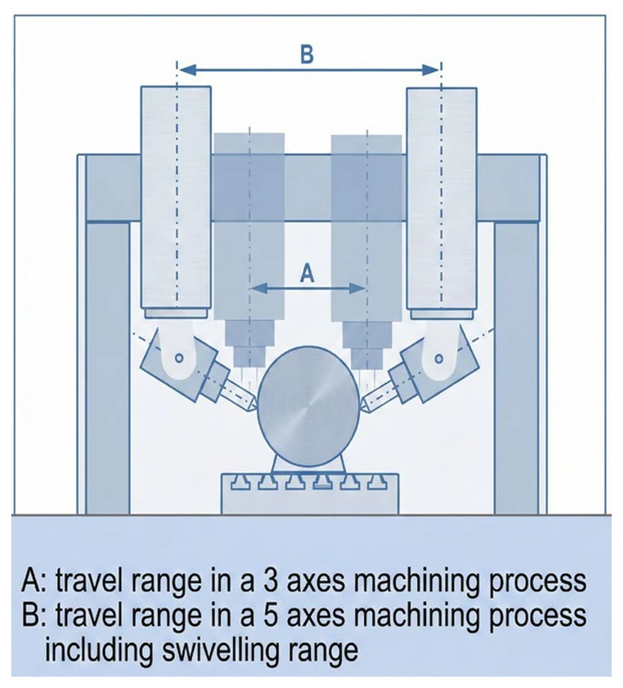
In a conventional 3-axis workflow, multi-sided components must be unclamped, flipped, and re-indicated across multiple operations. Every manual re-clamping introduces Datum Transfer Error (Tolerance Stack-up) caused by microscopic swarf, clamping force variations, and probing repeatability limits. Holding tight GD&T callouts—such as ±0.01 mm True Position or perpendicularity between opposing bores—becomes a constant struggle against scrap.
Furthermore, machining deep cavities on a 3-axis machine forces programmers to use long-overhang tools so the spindle nose clears vertical walls. By cantilever beam mechanics, tool deflection ($\delta$) increases with the cube of tool stickout length ($L^3$):
$$\delta = \frac{F \cdot L^3}{3 \cdot E \cdot I}$$
Doubling tool stickout increases deflection by a factor of eight, forcing drastic reductions in depth of cut and feed rate to avoid chatter. By tilting the workpiece on a 5-axis machine, the tool holder clears steep walls effortlessly with a short, stubby cutter—delivering superior surface finish, longer tool life, and up to 2–3× higher metal removal rates.
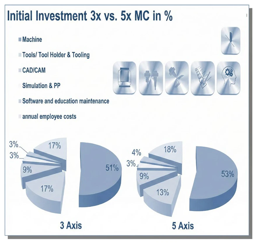
One of the most costly mistakes when transitioning to 5-axis manufacturing is allocating 100% of the capital budget to the machine tool while starving the surrounding technical ecosystem. As documented in Chapter 6 (p. 72) of The Art & Science of 5-Axis Machining, the Initial Investment Distribution Chart reveals a vital truth: the 5-axis CNC machine itself typically represents only ~30% of the total lifecycle ecosystem investment required to run at peak capability.
The remaining ~70% of the performance enablers consist of tightly integrated peripheral systems:
The golden economic rule of 5-axis machining is simple: “A 5-axis machining center only generates profit while the spindle is cutting chips—an idle machine waiting for manual setup is a pure economic loss.” Evaluating ROI therefore requires looking beyond hourly machine rate to Total Cost per Good Part and annual Spindle Utilization hours.
| Key Performance Indicator (KPI) | Conventional 3-Axis VMC | 5-Axis CNC (with Zero-Point Clamping) | Economic Impact |
|---|---|---|---|
| Setups per Complex Part | 4 Setups (120 min total) | 1 Setup (15 min offline/pallet) | 87.5% reduction in non-cutting setup time |
| Active Spindle Cutting Hours (per 8h shift) | 3.5 – 4.5 hours (~50%) | 6.5 – 7.2 hours (80–90%) | Nearly 2× higher daily throughput |
| Datum-Transfer Scrap & Rework Rate | 3% – 5% | < 0.5% | Major savings in exotic raw stock & rework |
| Typical Capital Payback Period | Baseline | 35% – 45% faster (18–24 months) | Unlocks high-margin aerospace & medical contracts |
By combining high-efficiency 3+2 indexed positioning (which accounts for 70–80% of real-world multi-sided parts) with simultaneous 5-axis surfacing and offline zero-point pallet preparation, manufacturers dramatically compress lead times and achieve a faster payback than adding multiple 3-axis machines.
© 2022 Machine Tech Co., Ltd. All Rights Reserved. Web design by 1001click.