From CAD/CAM to Shop-Floor Reality: Bridging the Digital-to-Physical Gap for High-Precision Parts
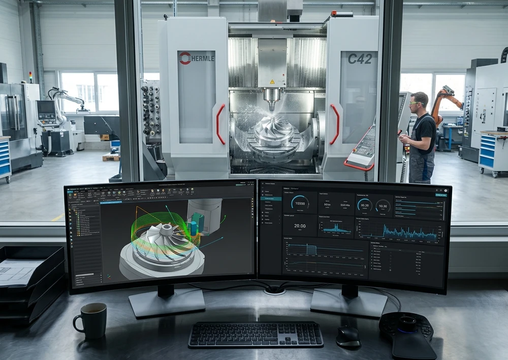
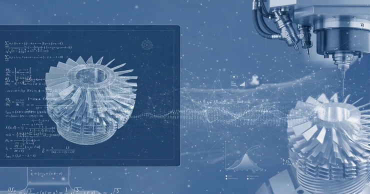
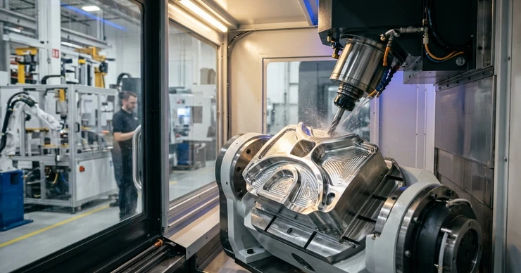
In high-precision 5-Axis CNC Machining, final part accuracy is determined long before the spindle starts turning. It is governed by the integrity of the entire digital-to-physical manufacturing chain: 3D CAD → CAM Strategy → Post-Processing → True G-Code Verification → Physical Machine Setup. A single mismatch between the virtual kinematic model in the programming office and the physical reality on the machine table can result in scrap, surface witness marks, or a catastrophic 5-axis collision.
Drawing from Chapter 6 (Manufacturing Process, pp. 48–79) of The Art & Science of 5-Axis Machining, this article provides a blueprint for bridging every gap between CAD/CAM programming and shop-floor execution—from spline surface continuity and mean-tolerance modeling to RTCP post-processing, Digital Twin verification, and 3D probe coordinate alignment.
Four Critical Bridges from Virtual CAD/CAM to Physical Precision
The 10-Milestone Process Backbone: Synchronizing engineering analysis, tooling preparation, programming, and shop-floor execution.
CAD Spline Continuity & Mean-Tolerance Modeling: Why surface quality on a 5-axis machine can never exceed the mathematical quality of the 3D CAD model.
Kinematic Post-Processing & True G-Code Digital Twin Simulation: Verifying real NC code rather than idealized CAM centerline data.
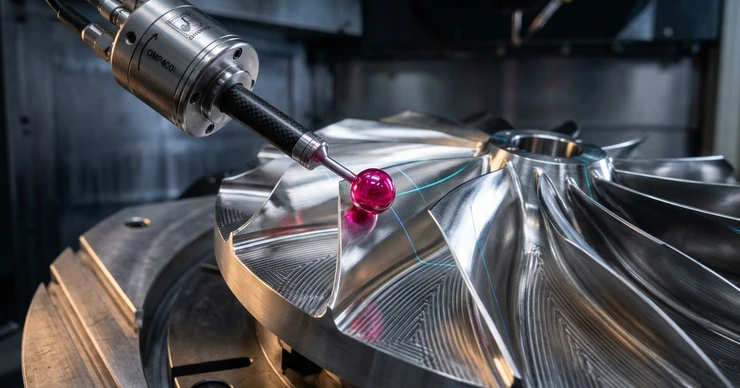
Physical Setup & Coordinate Alignment: Aligning the machine coordinate frame to the workpiece via 3D probing.
1. The 10-Step Process Backbone: Connecting Engineering and Production
As illustrated in Chapter 6 (pp. 48–49), if you hand the exact same technical drawing and 3D CAD model to ten different machine shops, you may see ten different machining approaches. However, every top-tier 5-axis facility relies on the same 10-Step Process Backbone to eliminate handoff errors:
Data Analysis: Feasibility validation of 2D drawings, GD&T tolerances, and 3D models.
Process Preparation: Cross-functional alignment on clamping concepts, operation sequences, and tooling lists.
3D CAD Preparation: Healing surface gaps, verifying spline continuity, and shifting critical features to mean tolerance.
Programming Approach Selection: Balancing office CAD/CAM programming with Workshop-Oriented Programming (WOP) where appropriate.
Post-Processing & Virtual NC Verification: Translating CL-data into machine-specific G-code and validating it in a kinematic Digital Twin.
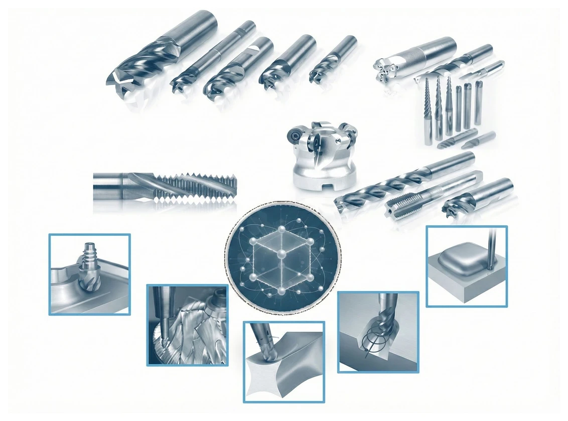
Offline Tool Preparation & Presetting: Assembling balanced holders, verifying TIR < 3 µm, and measuring exact gauge lengths.
Machine Setup & Coordinate Alignment: Mounting zero-point fixtures and aligning the WCS via 3D touch probing.
The Milling Process: High-utilization, stable chip making with in-process verification.
Standardization & Feedback Loops: Capturing proven feeds, speeds, and setup sheets into reusable CAM templates.
2. 3D CAD Surface Quality, Spline Continuity, and Mean-Tolerance Modeling
A fundamental law of digital manufacturing stated in Chapter 6 (pp. 57–58) is that “a 5-axis machined surface can never be smoother or more accurate than the underlying mathematical 3D CAD model.” Two CAD preparation pitfalls routinely sabotage high-precision parts:
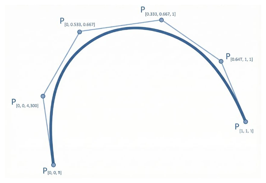
Spline Continuity ($C_0 / C_1 / C_2$) and Tessellation Tolerances: Freeform aerospace and mold surfaces rely on polynomial Spline / NURBS mathematics. If neutral file translations (STEP/IGES) or CAM chordal tolerances are set too loosely, smooth curvature degrades into micro-facets or tangent breaks. A high-response 5-axis CNC will faithfully machine those mathematical facets right onto the metal surface.
Mean-Tolerance Modeling for Asymmetric Callouts: Designers typically model 3D solids at nominal dimensions (e.g., $\varnothing 20.000\ \text{mm}$), while the 2D drawing specifies asymmetric tolerances such as $\varnothing 20^{+0.020}_{+0.000}\ \text{mm}$ ($\text{H7}$). Programming directly to the nominal 3D surface aims right at the lower rejection limit! Manufacturing engineers must shift critical CAD faces or CAM stock offsets to the mean tolerance value ($20.010\ \text{mm}$) to maximize process capability ($C_{pk}$).
3. Post-Processing and True G-Code Verification via Kinematic Digital Twins
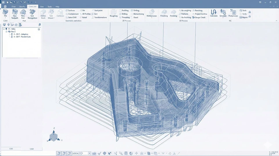
A CAM system calculates toolpaths as machine-independent cutter location data (CL-Data: tool tip $X, Y, Z$ and unit orientation vectors $I, J, K$). Translating that abstract geometry into executable motion is the job of the Post-Processor (pp. 68–70), which tailors output to the exact CNC kernel (e.g., Siemens TRAORI, Heidenhain TCPM / FUNCTION TCPM, Fanuc G43.4, Haas G234) and axis kinematics.
A critical danger lies in relying solely on basic internal CAM replay, which simulates idealized CL-Data before post-processing and remains blind to real-world machine behavior:
Unexpected rotary unwind/retract moves when an axis hits its physical travel limit.
Violent C-axis swings near the kinematic pole (Singularity point where tool vector approaches 0° tilt).
Rapid non-cutting linking moves, safe tool-change retracts, and fixture/trunnion collisions outside the cutting zone.
Bridging this gap requires True G-Code NC Verification in a Kinematic Digital Twin—simulating the actual post-processed G-code line by line against exact 3D models of the machine enclosure, rotary table, zero-point fixture, stock, and tool assembly.
4. Where Programming Meets Physical Reality: Tool Presetting and Coordinate Alignment
Chapter 6 (pp. 73–75) captures the ultimate truth of shop-floor execution: “Tool and machine setup is the exact point where virtual programming meets physical reality—a single discrepancy here instantly invalidates hours of precision CAD/CAM engineering.” Closing this final gap relies on two disciplined shop-floor practices:
Verified Tool Presetting & Collision Envelope Integrity: Physical tool stickout (gauge length) and holder profile must strictly match the Digital Twin collision model. Measuring exact tool length ($L$), diameter ($D$), and corner radius ($R$) on an offline optical presetter—and transferring offsets digitally via network or QR/RFID—eliminates manual data-entry crashes.
The Golden Rule of Coordinate Alignment (p. 74):“A classic and costly mistake is spending hours tapping a workpiece with a mallet to align it to the machine axes, instead of aligning the machine’s coordinate system to the workpiece!” On a modern 5-axis machine, operators clamp the part securely, probe two or three reference points with a 3D Touch Probe, and let the CNC controller rotate the active coordinate frame (3D Workpiece Alignment / Dynamic Work Offset) mathematically in seconds.